What is a Dynamic UPS?
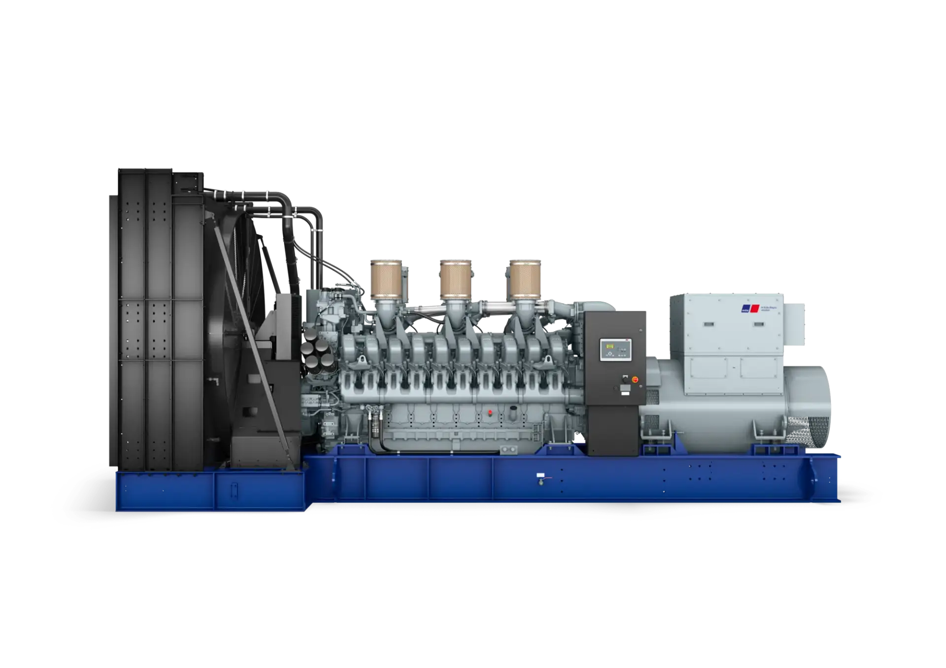
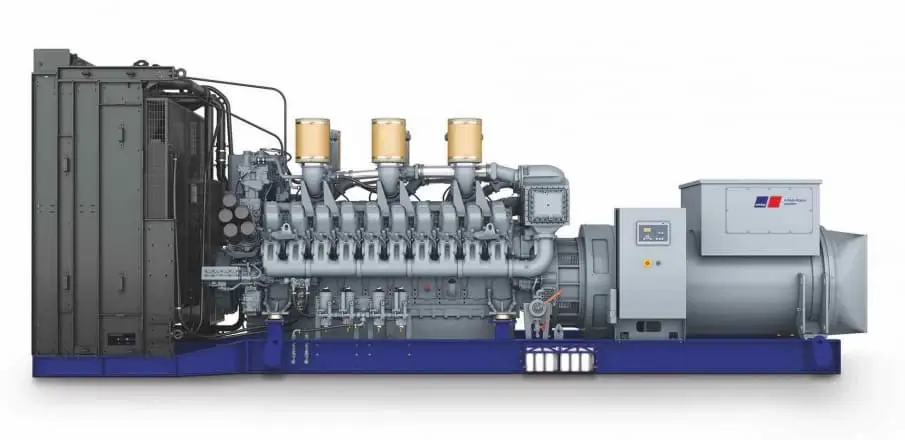
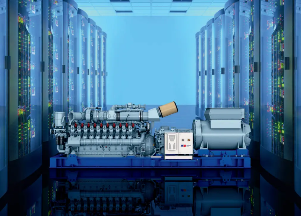
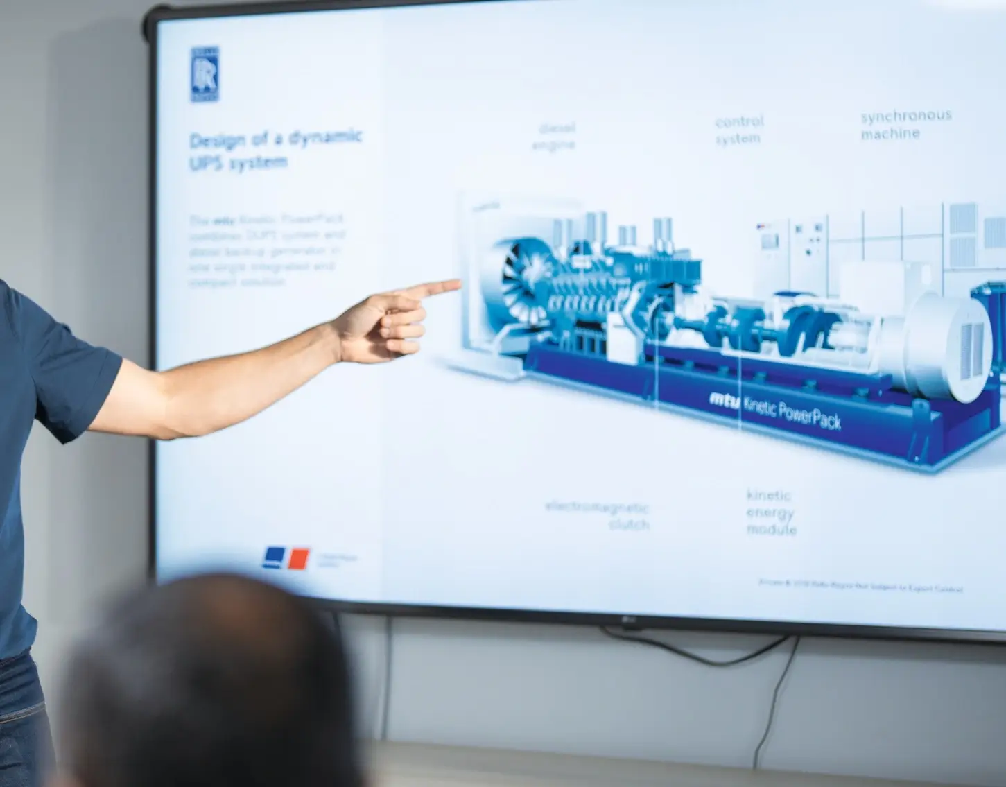
A Dynamic UPS or Rotary UPS (DRUPS) is a high-reliability power system that combines a diesel engine, synchronous generator, and kinetic energy storage (flywheel) into a single integrated unit. It provides uninterrupted power by storing energy mechanically and instantly supporting the load during grid disturbances, while the diesel engine starts to deliver long-term backup. Unlike static UPS systems, it does not rely on batteries for ride-through, making it highly robust, efficient, and well-suited for mission-critical applications such as data centers, airports, healthcare facilities and industrial facilities.
Two Modes of DRUPS Operation
Conditioning Mode: In this mode, the Dynamic UPS operates with the utility power available and within acceptable limits. The system conditions the incoming power stabilizing voltage, filtering disturbances, and maintaining frequency while keeping the kinetic energy storage (flywheel) fully charged and ready to respond instantly to any power interruption.
Independent Mode: In independent mode, the Dynamic UPS operates without reliance on the utility supply (Utility failure). The diesel engine is engaged and, together with the kinetic energy storage, continuously supplies stable and uninterrupted power to the load, ensuring full autonomy during utility failure or when operating in island mode.
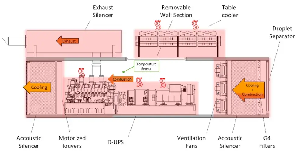
DRUPS room ventilation introduction
Dynamic UPS or Rotary UPS (DRUPS) rooms housing diesel engines, accumulators (Fly wheels) and alternators concentrate heat sources, and combustion processes within a confined environment. Temperature increase within the room can negatively affect the personnel, machine performance, and other equipment exist in the room like switchgears.
Unlike normal generators, the heat sources exist in their two modes whether engine is running or not. The reason is that the alternator and accumulators are continuously running to provide conditioned power to the sensitive loads.
A properly engineered ventilation system ensures:
- Adequate cooling air for heat removal
- Sufficient combustion air for engine operation
- Acceptable ambient conditions for equipment and personnel
Heat Sources During DRUPS Operation
Conditioning mode
Accumulators (Flywheel) – Values provided by manufacturer
Alternator (Acting as a motor to drive the accumulators) – Values provided by manufacturer

Independent mode
Engine: Can be found within the engine technical data sheet
Alternator: Heat can be estimated from the following equation:
Where:
H = Heat radiated
P = Generator output at maximum engine rating (ekW)
Accumulators (Flywheels)
- Accumulators
- Exhaust piping
Combustion Air for DRUPS Operation
Diesel engines included in dynamic UPS (DRUPS) system require a continuous air supply for combustion during independent mode:
Approximate requirement:
- 1 m³/min per brake kW (≈2.5 cfm per bhp) – Refer to Engine datasheet
Design approaches:
- Dedicated ducted combustion air (preferred)
- Engine room air intake (requires larger ventilation capacity)
Ventilation Airflow Calculation
The required ventilation airflow is calculated using the following equation:

Where:
- V = Airflow
- H = Total heat rejection
- D = Air density (1.204 kg/m3 @25 deg.c)
- Cp = Specific heat of air (1.005 kJ/kg.K @25 deg.c)
- ΔT = Allowable temperature rise (According to manufacturer guidelines)
Ensuring Reliable Generator Performance
Engine room ventilation is not just an auxiliary system it is a critical performance and reliability factor.
A properly engineered system ensures:
- Maximum generator efficiency
- Safe operating environment
- Compliance with international standards
At Al Masaood Power, our engineering team carefully evaluates ventilation, heat loads, and operational modes to ensure that every Generator installation performs reliably under real operating conditions.
Related Standards
- NFPA 110